 Everything
You Ever Wanted to Know About Hubs But Were Afraid to Ask
Everything
You Ever Wanted to Know About Hubs But Were Afraid to Ask
Over the years, Willys used many different types of locking hubs for the front axle. There were also many manufacturers of aftermarket hubs that were installed.
 |
 |
| The Cutlass Power-Lock Hub | The Dualmatic Hub |
Here are a series of articles on the hubs by Rick Stivers and Rob Wolfe
Cutlass Power-Lock-Hub
THIS WEB PAGE WAS A FAMILY PROJECT
Text by: Rick Stivers
Photos by: Stephanie Stivers age 12
This is the Cutlass Power-Lock-Hub (PLH). Cutlass Tool and Mfg. Co Lyons Ill manufactured them. I have been unable to locate this company so it seems that they have either gone out of business or merged with some other company. If you locate this company, please contact me so that I can update this page.
The PLH is locked and unlocked using the angled tool in the picture known a
control key. Each end of the tool is rounded to fit into the curved slots in the
top of each locking pin on the hub. The locking pins have arrows to determine if
they are locked or unlocked. When the arrows point out the hub is unlocked, when
they point in it is locked. The hubs should be locked before engaging the
four-wheel drive so that the axle shaft can be turned internally. Failure to
lock the hubs prior to engaging the four-wheel drive usually causes the hub to
bind and prevents locking. The Hub has these instructions printed on the face:
|
" IMPORTANT SHIFT TRANSFER CASE TO 2 WHEEL DRIVE & TRANSMISSION TO NEUTRAL DIRECTION OF ARROWS 3 2 WHEEL DRIVE 44 4 WHEEL DRIVE 3 " |
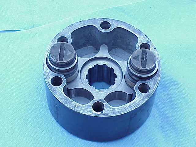 With the hub's cover removed it is easy to see the locking pins in the locked
position.
With the hub's cover removed it is easy to see the locking pins in the locked
position.
 Note the cutout in the locking pin. When the pin is locked the cutout is rotated
to the outside edge of the hub and then the drive gear can free wheel inside the
hub. The locking pin assembly consists of the pin, spring, seal (O-ring), and
washer. The spring preloades the locking pin down into a locked position (More
on this later). The O-ring seals the cam-lock and the washer prevents the spring
from cutting into the soft brass face on the locking pin when the pin is
rotated.
Note the cutout in the locking pin. When the pin is locked the cutout is rotated
to the outside edge of the hub and then the drive gear can free wheel inside the
hub. The locking pin assembly consists of the pin, spring, seal (O-ring), and
washer. The spring preloades the locking pin down into a locked position (More
on this later). The O-ring seals the cam-lock and the washer prevents the spring
from cutting into the soft brass face on the locking pin when the pin is
rotated.
 A close-up of the locking pin in the unlocked position allows you to observe how
the drive gear can rotate through the unlocked pin.
A close-up of the locking pin in the unlocked position allows you to observe how
the drive gear can rotate through the unlocked pin.
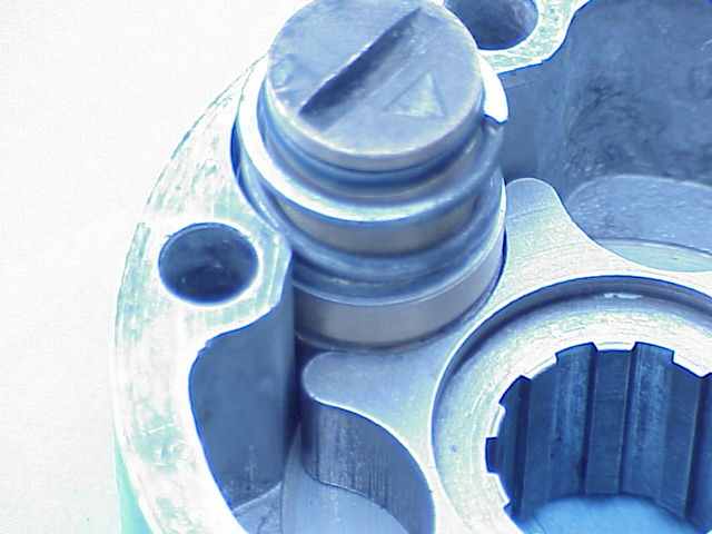 The same pin has been rotated into the locked position. In this position the
drive gear is locked in place and this transfers power to the wheel. Failure to
lock both cams on a hub could cause severe damage to the hub by transferring all
of the power to one side of the hub.
The same pin has been rotated into the locked position. In this position the
drive gear is locked in place and this transfers power to the wheel. Failure to
lock both cams on a hub could cause severe damage to the hub by transferring all
of the power to one side of the hub.
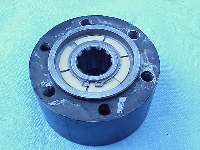 In this bottom view of the PLH you can see the nylon bearing that is the
Achilles' Heel of the hub. The drive gear rotates on this bearing. Apparently
the bearing worked well and didn't need to be stronger when new. However after
30 years or so, they are starting to crack.
In this bottom view of the PLH you can see the nylon bearing that is the
Achilles' Heel of the hub. The drive gear rotates on this bearing. Apparently
the bearing worked well and didn't need to be stronger when new. However after
30 years or so, they are starting to crack.
 Here is the bearing with the drive gear removed.
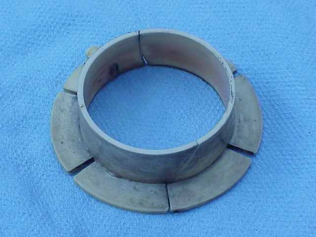 Here is the bearing removed from the hub. It looks pretty good at first glance.
 But in this view its condition takes on a different light. The straight cut is
factory original but the one in the back is not. Even with the bearing cracked
in half, the hub still works fine.
But in this view its condition takes on a different light. The straight cut is
factory original but the one in the back is not. Even with the bearing cracked
in half, the hub still works fine.

 The old WARN Hubs, that I used to replace my Cutlass Hubs, have a set of caged
needle bearings in the place of the nylon bearing. This gives you a pretty good
idea of the difference in quality. If this bearing had been made of brass or
bronze I think it would have been a lot better. I had no idea where to find new
bearing for these hubs, so I changed to the WARN Hubs. I could have bought a new
set of hubs but new parts on an old truck look funny to me. I bought these WARNs
are off of a 1949 Willys Pickup that was on its way to the junkyard.
The old WARN Hubs, that I used to replace my Cutlass Hubs, have a set of caged
needle bearings in the place of the nylon bearing. This gives you a pretty good
idea of the difference in quality. If this bearing had been made of brass or
bronze I think it would have been a lot better. I had no idea where to find new
bearing for these hubs, so I changed to the WARN Hubs. I could have bought a new
set of hubs but new parts on an old truck look funny to me. I bought these WARNs
are off of a 1949 Willys Pickup that was on its way to the junkyard.
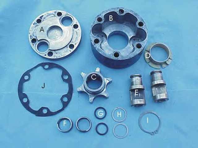 Here is a photo of the individual parts of the hub. If the plastic ring is still
usable like mine then you can just replace the o-rings and make a set of gaskets
to seal it up. Note the complex design of the homemade gasket. It has to be cut
his way to prevent the center hub from catching on the gasket. I learned this
the hard way. My bottom gasket did not survive the removal so it isn't in the
picture.
Here is a photo of the individual parts of the hub. If the plastic ring is still
usable like mine then you can just replace the o-rings and make a set of gaskets
to seal it up. Note the complex design of the homemade gasket. It has to be cut
his way to prevent the center hub from catching on the gasket. I learned this
the hard way. My bottom gasket did not survive the removal so it isn't in the
picture.
| A. Cover | C. Drive Gear | E. Lock Pins | G. Seals | I. Retaining Ring |
| B. Housing | D. Nylon Bearing | F. Springs | H. Flat Washers | J. Top Gasket |
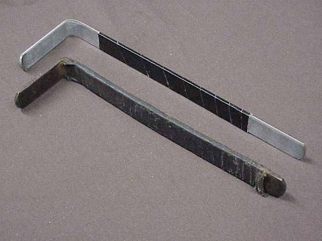 I decided to make a new set of control keys. I used a piece of 3/4" bar steel.
They were cut to about 14" long and then the last 4" were bent over at a
90-degree angle. I put a quarter on the end and drew a circle on the bar stock.
The circle was used to grind the end into a smooth curve. I chose a quarter
because it fit the curve in the locking cam perfectly.
I decided to make a new set of control keys. I used a piece of 3/4" bar steel.
They were cut to about 14" long and then the last 4" were bent over at a
90-degree angle. I put a quarter on the end and drew a circle on the bar stock.
The circle was used to grind the end into a smooth curve. I chose a quarter
because it fit the curve in the locking cam perfectly.
REMOVAL AND DISASSEMBLY PROCEDURES
The first step in removing the Cutlass Hub is to remove the six bolts holding the Cover in place.
Remove the cover. The brass Locking Pins may or may not come off with the cover, it doesn't matter.
Using snap-ring pliers, remove the snap-ring from the axle stub. Now the rest of the hub will come off.
If the Locking Pins stayed inside the hub, you can remove them now.
You may need to rotate the Drive Gear to release the Locking Pins.
Remove the Locking Pin Springs and Washers.
The Seals should be removed and replaced. The seals are nothing more than O-rings that can be purchased in most parts houses.
Turn the Housing upside down and remove the Retaining Ring from the drive gear.
Remove the Drive Gear from the front and the Nylon Bushing from the rear.
INSPECTION PROCEDURES
Remove all grease and dirt from the parts and inspect for damage.
1. Inspect the cover and housing for cracks and chips.
2. Inspect the Drive Gear and Locking Pins for excessive wear. The Locking Pins have a cam lobe on the bottom that if worn away will prevent the Locking Pins from locking in place. Fit the Pins into the Housing and ensure that they turn smoothly. The outside end of the Locking Pins has a curved slot cut into it. If it needs to be repaired, you can do it with a Dremal tool.
3. Inspect the Locking Pin Springs to ensure the are not broken and that they will not bind on the Pins.
4. Inspect the Nylon Bearing for cracks. If it is only broken in half it can still be used but if it is crumbled, some type of replacement will be needed. I am trying to have some brass or bronze bushings made for these hubs. If I am successful, I will post it here.
5. The Seals should be replaced to prevent grease from escaping the hub and to keep moisture out.
INSTALLATION PROCEDURES
New gaskets are not available so homemade gaskets will need to be made. The bottom gasket is fairly easy to make because it doesn't have any compound curves. The top gasket must be cut to allow the center hub to move freely inside the hub housing, without hitting on the gasket.
Slide the Nylon Bearing inside the Housing from the backside.
Slide the Drive Gear into the Housing from the front side and install the Drive Gear Retaining Ring.
Slide the Locking Pin Washers onto the Pins then slide on the Locking Pin Springs.
Install the Locking Pins into the Housing with the openings toward the middle.
Rotate the Drive Gear until it engages the Locking Pins. This will hold them in place until the cover plate can be installed.
Fit the bottom gasket onto the Housing and the top gasket onto the Cover.
Slide the Housing over the axle stub (No force should be needed) and install the snap ring.
Install the Cover and six bolts. Cross torque the bolts to prevent the hub from binding.
CUTLASS HUB ORIGINAL BOX
 Now someone has even provided a picture of the original Cutlass Hub box label.
This is great. For a larger, more detailed picture you can click on the picture.
Now someone has even provided a picture of the original Cutlass Hub box label.
This is great. For a larger, more detailed picture you can click on the picture.
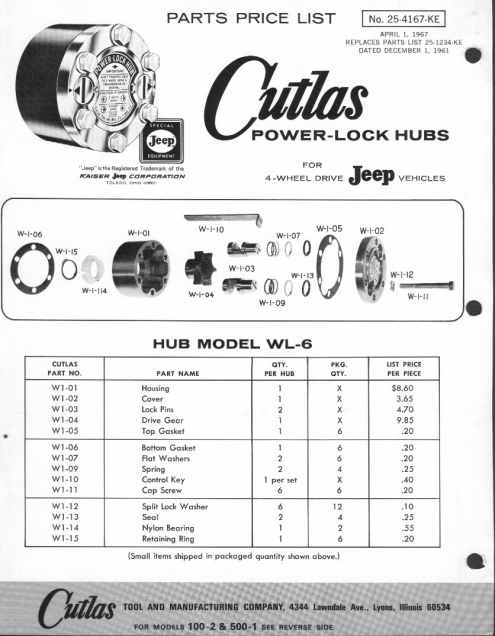 As if that
wasn't enough Jeff Bonno was kind enough to supply me with this wonderful scan
of an illustrated parts breakdown of this hub and another Cutlass Hub. For a
nice viewable picture click on the thumbnail. For a really large printable
file, you can click
here.
As if that
wasn't enough Jeff Bonno was kind enough to supply me with this wonderful scan
of an illustrated parts breakdown of this hub and another Cutlass Hub. For a
nice viewable picture click on the thumbnail. For a really large printable
file, you can click
here.

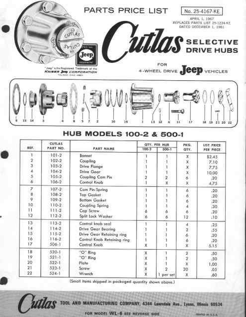 Here is
the other Cutlass Hub.
Here is
the other Cutlass Hub.
Dualmatic Hubs
By Rob Wolfe

These hubs use 2 levers to lock and unlock the front axels. If you look at the lever on the edge it will
have a locked and free stamped on opposite sides of the lever.
To operate the hubs you just pull up on the lever and turn it 180 degrees and lock it back down.

This is the inside section of the hub and it butts up the the wheel hub.
There should be a gasket in between them.

This shows the inside of the hub.
The drive axel goes through the star gear.
If The star gear is free to spin, no force will be transferred to the wheel/tire.
If the star gear is locked into position, then the force from the axel is applied to the wheel/tire.


This shows the hub in the free position. The star gear is "free" to spin in the hub.


This shows the hub in the locked position. The star gear is now captured by the hub rollers and
power will be transferred to the wheel/tire.

Here one side of the hub is locked and the other is free.
This will put a lot of pressure on the locked side which could break the hub.
I have herd of people painting the locked edges red and the free ones green to make it easier
to make it easier to see and thus prevent.

Some times the levers will be very hard to turn as they may be sitting in to far.
To fix that you just put a gasket between the 2 hub pieces.
The bolts holding the hub on also have a tendency to come loose. Use LockTite on them to keep that from happening.

Each lever has a set screw (circled) that is used to keep the levers from coming loose while driving.
You can tighten it up a little so that the lever snaps in place. There is a hole in the lever for the screw to snap into.